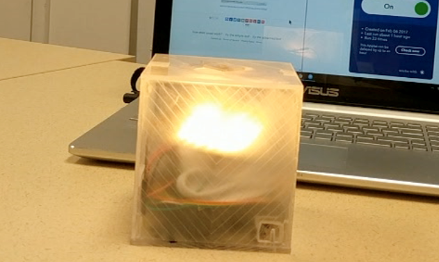
The goal of this IoT project is to create an ambient desktop device that reminds you to check your email inbox. The motions and color of the box reflect the mounting stress and anxiety reflect how you feel when you procrastinate checking your email. Once you sit down to check email and reset the box, it reflects a calmer state to help you focus.
0
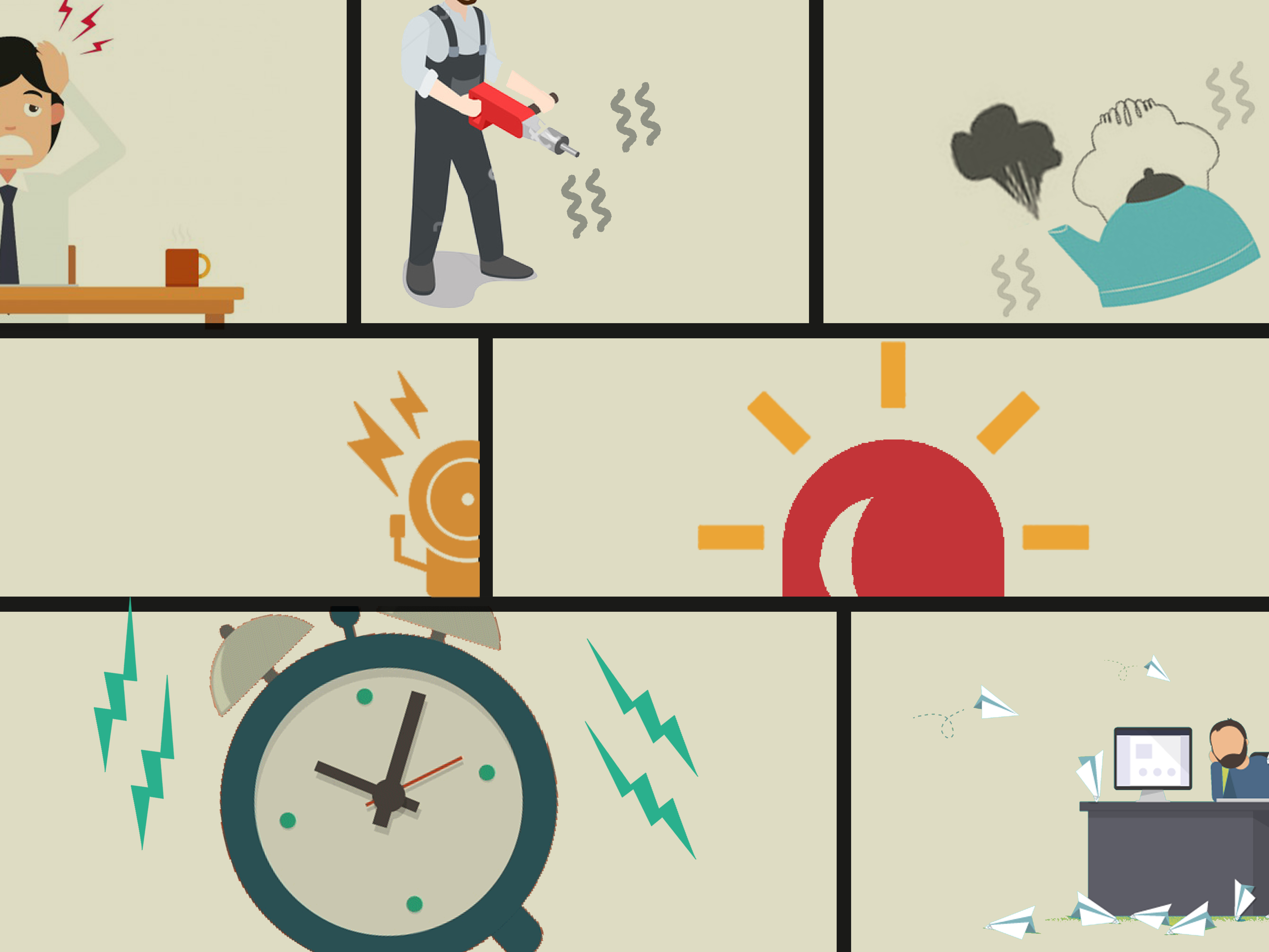
We all procrastinate checking our email sometimes, letting it pile up in our inboxes. The longer you wait, the worse you feel. Your stress and anxiety inch upward with every tick of your Unread Email count. We wanted to make a device that reflected this emotion, while also encouraging you to check your email before the stress gets too high.
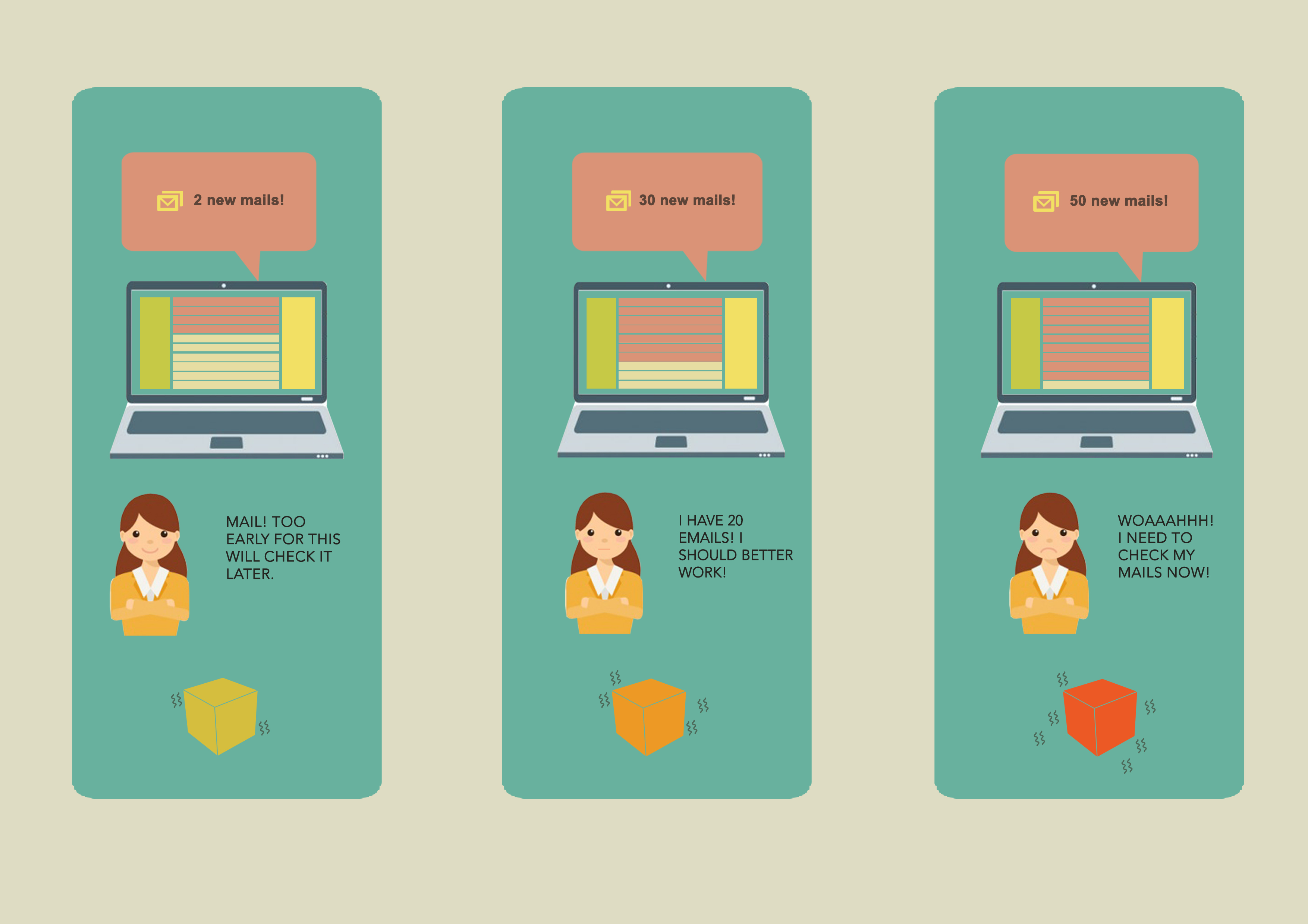
The Freakout Box could sit on your desk, somewhere in your home, or at work; where ever you might be while ignoring your emails. When your new unread email count reaches the first threshold, the Freakout Box lights up and begins gently buzzing. When the emails reach the second level, the box turns orange and buzzes more urgently. When the email count reach final threshold, the box turns red and is out of control! You will be deterred from letting reach the final level because it is so stress inducing. When you are ready to sit down and check your mail, you can hit the reset button on the box to return it to a calm state.
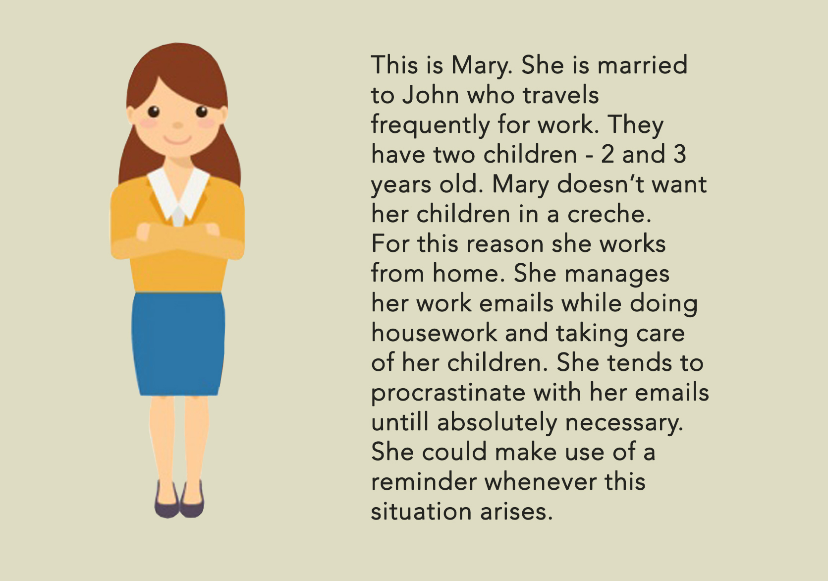
We initially were motivated by the emotion of stress and wanted to reflect that emotion in a physical object. We gathered the images below in a mood board to inspire our design. We particularly zeroed in on the feeling you get when your email inbox fills up but you put off checking it. We created a persona and storyboard about how our device might work in the life of a user.
Process & Challenges
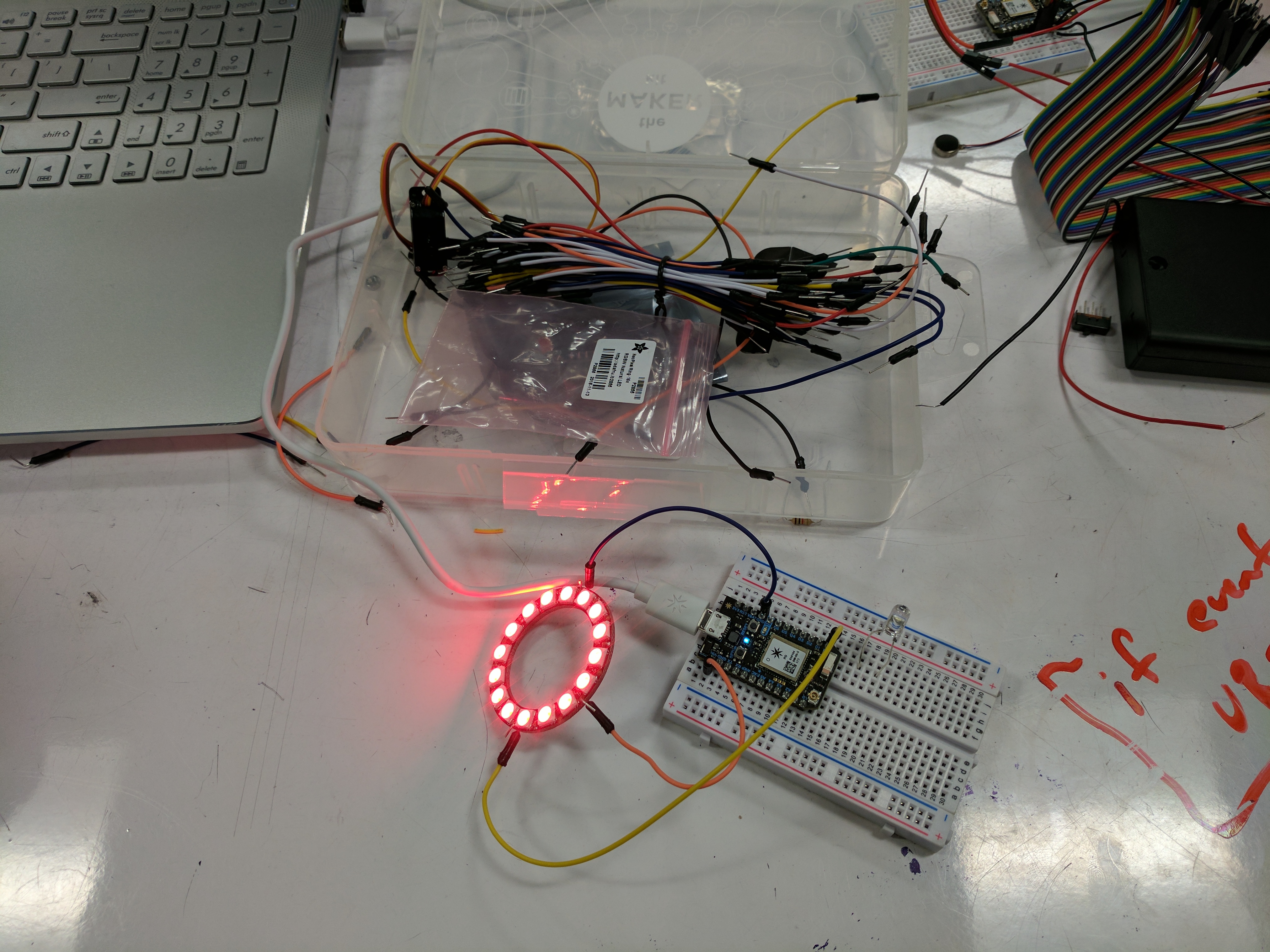
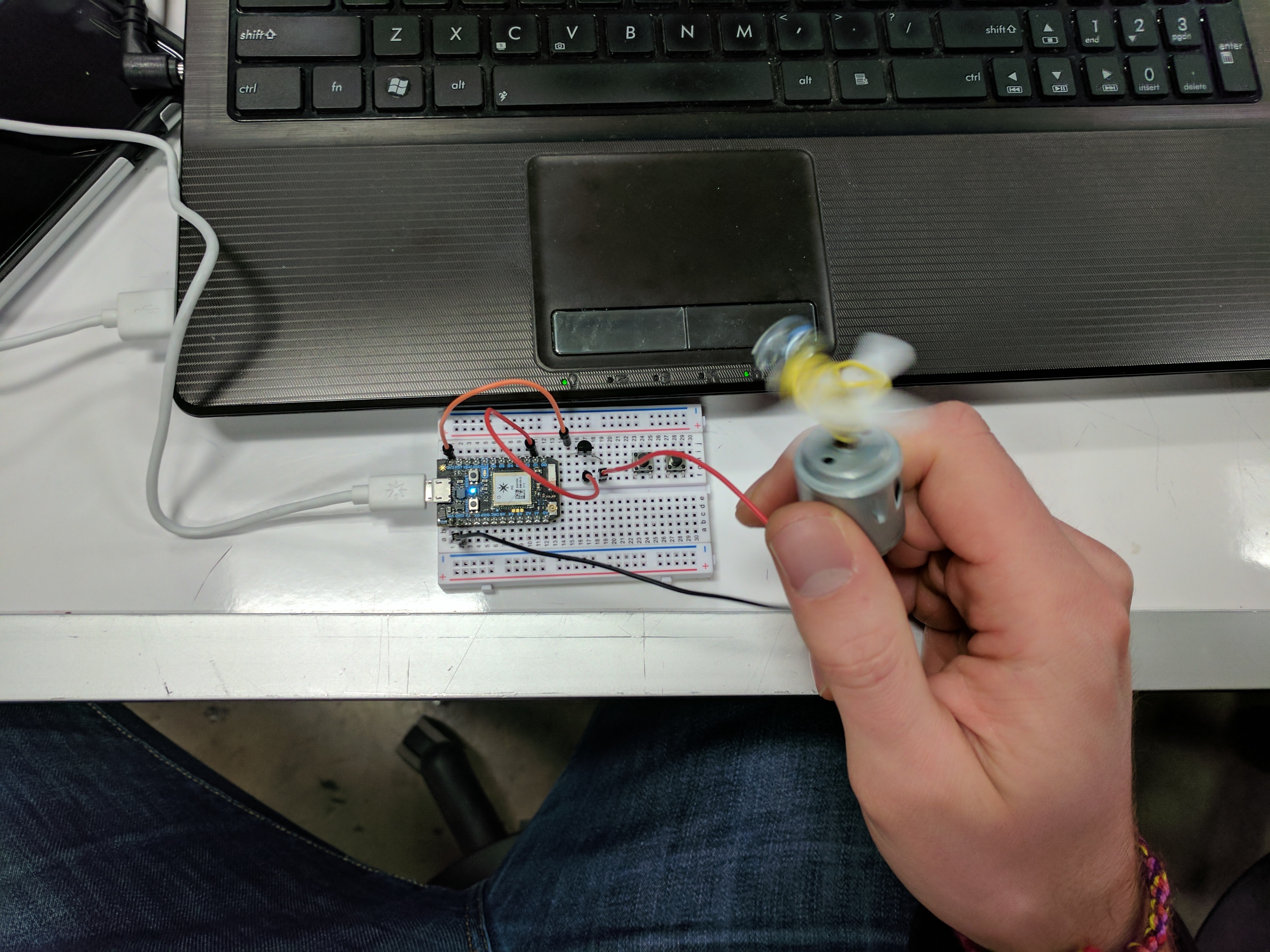
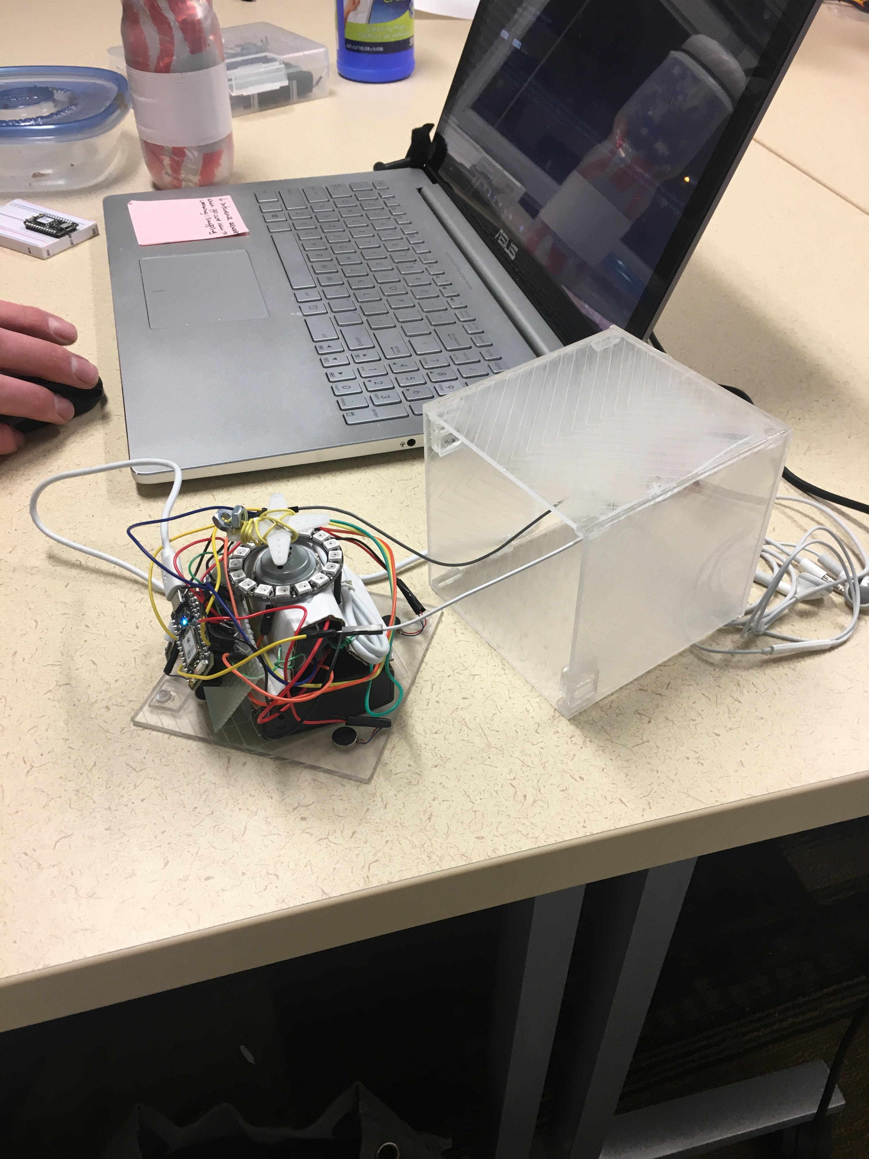
After brainstorming the concept and design, we each worked on wiring and initiating 1 of the 3 outputs: vibrators, DC motor, and LED ring. Once each piece was working individually, it was assembled together.
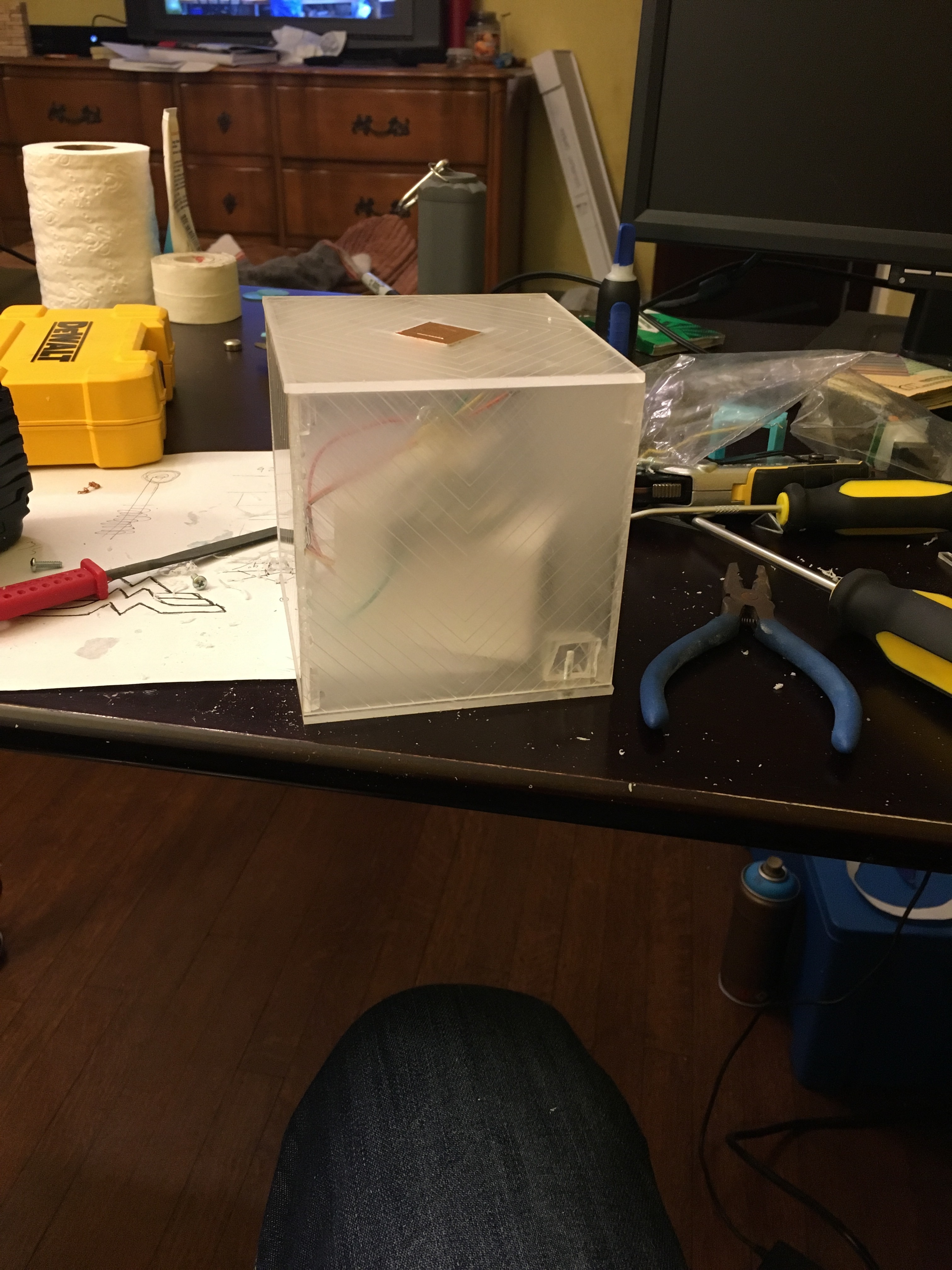
While assembling the circuit hardware, we faced four barriers: The volume of the cube, the rigorous vibration caused by the motor, the possible collision of the DC motor with internal components, the power draw from the DC motor and a poorly performing capacitive sensor. After assembling the acrylic cube, we realized we had set a space constraint for ourselves. While we desired to make the cube an unobtrusive size, we still needed to fit electronics in it. In addition to all the vibrators, the LED ring and DC motor, we had to fit a battery pack to power the entire system. This space constraint was one reason we decided not to use a breadboard in our prototype. The other reason we could not use a breadboard was because of the rigorous vibration our DC motor (intentionally) caused the entire cube to experience. Given the poor connections often experienced in breadboards, the vibration would inevitably cause a few wires to jump out of the board. Due to the vibration and the space constraints, we decided to solder the photon directly to a board and the required components.
The space constraints also raised a concern on potential collisions inside the device involving the DC motor spinner and everything else in the device. If the device is not assembled correctly, the DC motor will entangle any nearby components. Finally, the voltage and current draw required by the motor has the potential to disrupt the use of the button. Due to the way we have the system wired, the button is supplied with less current/voltage when the DC motor is first starting. In future revisions of this device, we would change our button from an analog to a digital input. On the subject of buttons, we initially attempted to use a capacitive sensor instead of a mechanical button. Due to the way we had the copper strip oriented, the sensor was not reliable. We solved this problem by moving to the more reliable mechanical button.
When assembling together the pieces of code, we created an IFTTT trigger from gmail, and then used that to create an unread email counter. This counter then triggered the different states of the box, with different colors and motor configurations. Surprisingly, the button was the most difficult part of the code.
Outcome
The following video showcases the capabilities of the FreakOut Box. With new emails, the box increments up to each new stress level - yellow, orange, and red. When the user is ready to sit down and check email, they can reset with the button on top. The button is also able to flip on and off the LED when not in use.
Notes of the video: to test the box, we are using an email testing service and manually triggering IFTTT in the background due to its slow output speed. The trigger levels are each set at 1 increasing email, so each email sends the box to a new stress level.
Email_Alarm_bb.pdf
610.193 KB · Download / View
//LED library setup
#include "neopixel.h"
#include <math.h>
//capacitive library setup
//#include "captouch.h"
//#define CAPTOUCH_DEBUG

// IMPORTANT: Set pixel COUNT, PIN and TYPE
#define PIXEL_PIN D0
#define PIXEL_COUNT 16
#define PIXEL_TYPE WS2812
Adafruit_NeoPixel strip = Adafruit_NeoPixel(PIXEL_COUNT, PIXEL_PIN, PIXEL_TYPE);

//push button
int buttonPush = A2;
// Pin numbers for vibrating discs
int vib1 = D4;
int vib2 = D5;

// pin number for motor
int Motorpin = D1;

//Levels of counter
int unread = 0;
int timeHeld = 0;
int level1 = 1;
int level2 = 2;
int level3 = 3;

void setup()
{
  //LED setup
  strip.begin();
  //for(i=0; i< strip.numPixels(); i++)
  //strip.setPixelColor(i, 0, 0, 0 );//white
  strip.show(); // Initialize all pixels to 'off'

// Set pins to output, meaning info flows from particle to component (vibrating discs)
pinMode(vib1, OUTPUT);
pinMode(vib2, OUTPUT);
pinMode(Motorpin, OUTPUT);

// Set all outputs to off to begin
digitalWrite(vib1, LOW);
digitalWrite(vib2, LOW);
digitalWrite(Motorpin, LOW);

//listening for IFTTT trigger for Gmail
Particle.variable("unread", &unread, INT);
Particle.subscribe("NewEmail", myHandler);
Serial.begin( 9600 );
Serial.print("startup");
}


void loop()
{
  int buttonState = analogRead(buttonPush);
  delay(50);
  //Serial.print(timeHeld);
  //Serial.print("");
  //Serial.print(buttonState);
  //Serial.print("   ");
  //when button is pressed, reset unread count to zero
if (buttonState <600 ){
  unread = 0;
  Serial.print("reset");
  Serial.print(unread);
  Serial.print("  ");
  //timeHeld is triggered if button is held down for a few seconds
  timeHeld++;
  if (timeHeld > 60){
  timeHeld = 0;
}
}
//when DC motor is running in level 3, analog output of button is different, needs its own if
if (buttonState >2000 ){
  unread = 0;
  Serial.print("reset");
  Serial.print(unread);
  Serial.print("  ");
  timeHeld++;
  if (timeHeld > 60){
  timeHeld = 0;
}
}
if (unread ==0){
  if (timeHeld > 30){
    //if button is held down for a few seconds, turn off the lights
    uint32_t i;
    for(i=0; i< strip.numPixels(); i++)
    strip.setPixelColor(i, 0, 0, 0 );//lights off
    strip.show();
  }else{
  breathe();
  //delay(50);
  digitalWrite(vib1, LOW);
  digitalWrite(vib2, LOW);
  digitalWrite(Motorpin, LOW);

}

}

}


void myHandler(const char *event, const char *data){
unread++;//when handler gets a NewEmail event, increment unread count
//Serial.print("email");
//Serial.print(unread);
checklevelchangestate();
}

//function to change state of cube
void checklevelchangestate(){
Serial.print("checking level");
if ( unread <= level1)
{
  Serial.print("level");
  Serial.print(level1);
  //turn the first level of vibrators
  digitalWrite(vib1, HIGH);

  // Turn on LED to yellow
  uint32_t i;
  for(i=0; i< strip.numPixels(); i++)
  strip.setPixelColor(i, 255, 96, 0 );//yellow
  strip.show();

}else if(unread <= level2){
    Serial.print("level");
    Serial.print(level2);
      // We'll turn the all vibrators
        digitalWrite(vib1, HIGH);
        digitalWrite(vib2, HIGH);

        // Turn on LED to orange
        uint32_t i;
        for(i=0; i< strip.numPixels(); i++)
        strip.setPixelColor(i, 255, 20, 0 );//orange
        strip.show();

}else if(unread <= level3){
    Serial.print("level");
    Serial.print(level3);
      // We'll turn the first level of vibrators
        digitalWrite(vib1, HIGH);
        digitalWrite(vib2, HIGH);
        digitalWrite(Motorpin, HIGH);
          // Turn on LED to red
            uint32_t i;
            for(i=0; i< strip.numPixels(); i++)
            strip.setPixelColor(i, 255, 0, 0 );//red
            strip.show();
}
}


float breathe( ){

  float val = (exp(sin(millis()/2000.0*M_PI)) - 0.36787944)*108.0;
  //Serial.println( val );

  uint16_t i;
  uint32_t c = strip.Color(val, val, val);

  for(i=0; i< strip.numPixels(); i++) {
    strip.setPixelColor(i, c );
  }
  strip.show();

}
Sources
Connecting Gmail to particle via IFTTT: https://ifttt.com/create/if-any-new-email-in-inbox-then-publish-an-event?sid=5
Vibrator Hack : https://www.ackster.io/nyl/buzz-wolf-837db0?ref=search&ref_id=particle%20vibration&offset=2
LED ring: Daragh’s Breathe code
Share this Project
Found In
Courses
49-713 Designing for the Internet of Things
· 26 members
A hands-on introductory course exploring the Internet of Things and connected product experiences.
Focused on
About
The goal of this IoT project is to create an ambient desktop device that reminds you to check your email inbox. The motions and color of the box reflect the mounting stress and anxiety reflect how you feel when you procrastinate checking your email. Once you sit down to check email and reset the box, it reflects a calmer state to help you focus.
Created
February 7th, 2017