Kiche.Net of Things: Connected Photo
Made by Dan Porter, Lauren Romero, Alok Joshi and Hsiao-Ting Hung
Found in Connected Cuisine
-
Kiche.Net - Photographic Memory
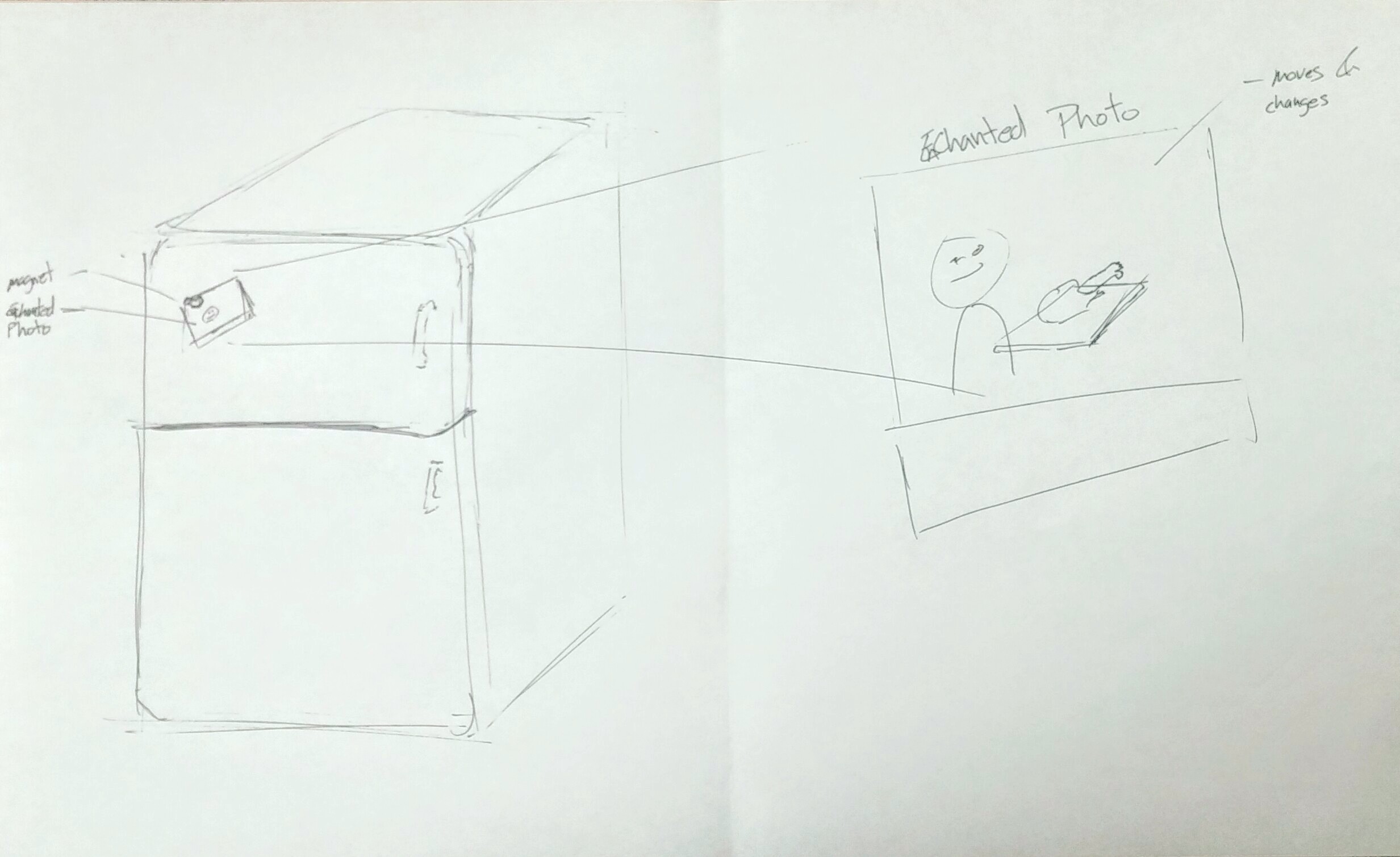
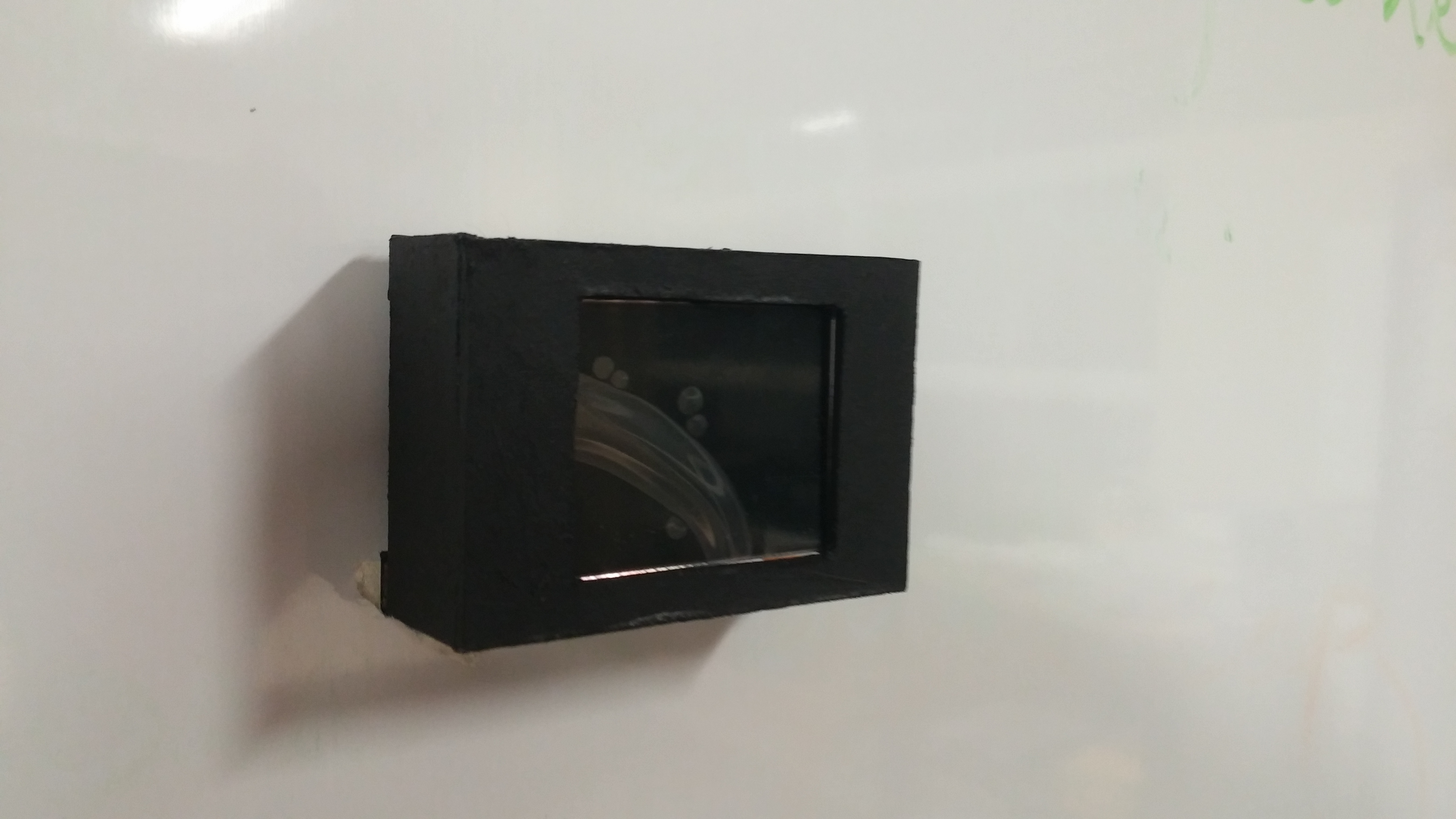
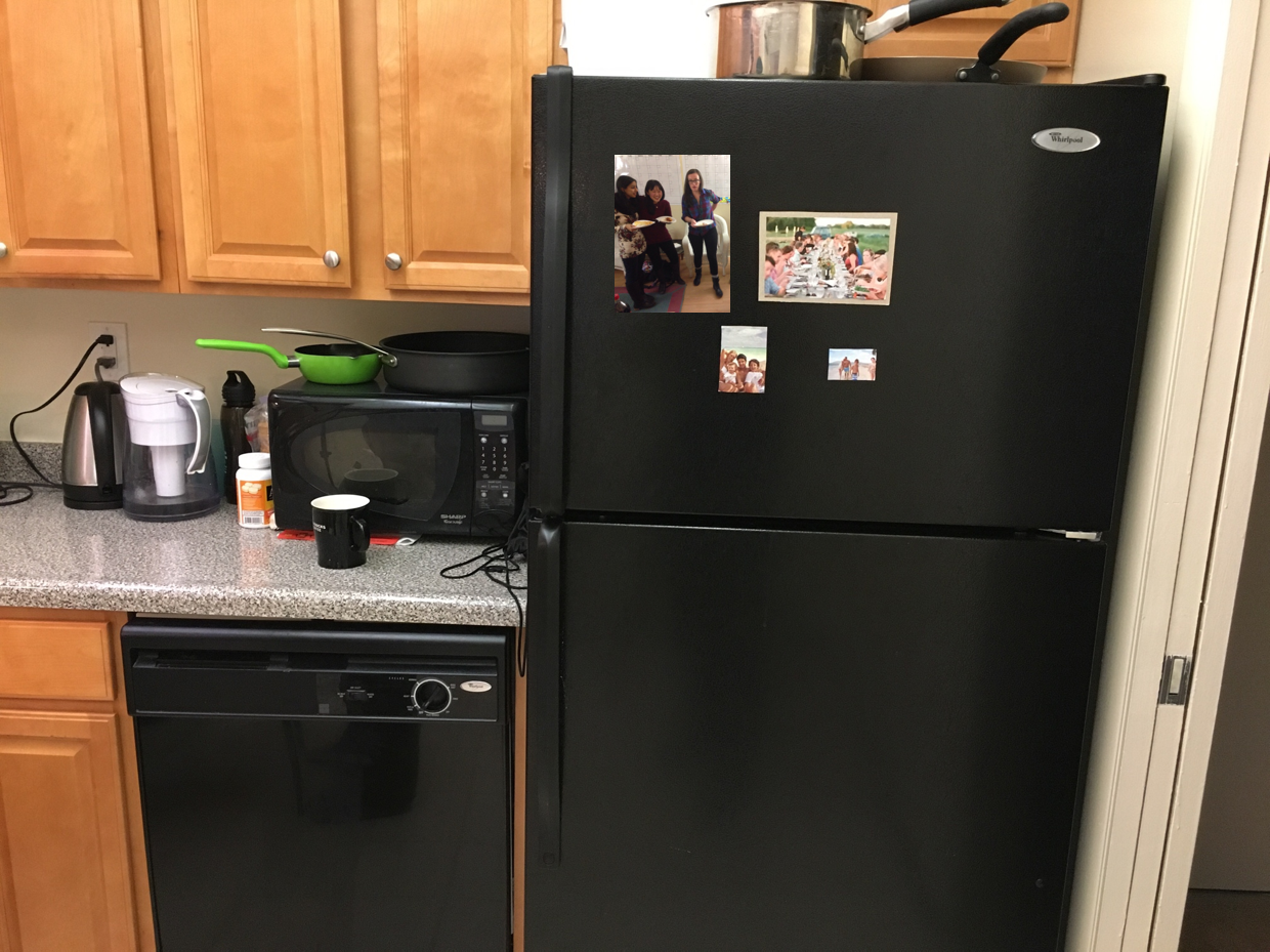
The Connected Photo reminds users of fond memories related to the dish they are cooking
Functionality Objective
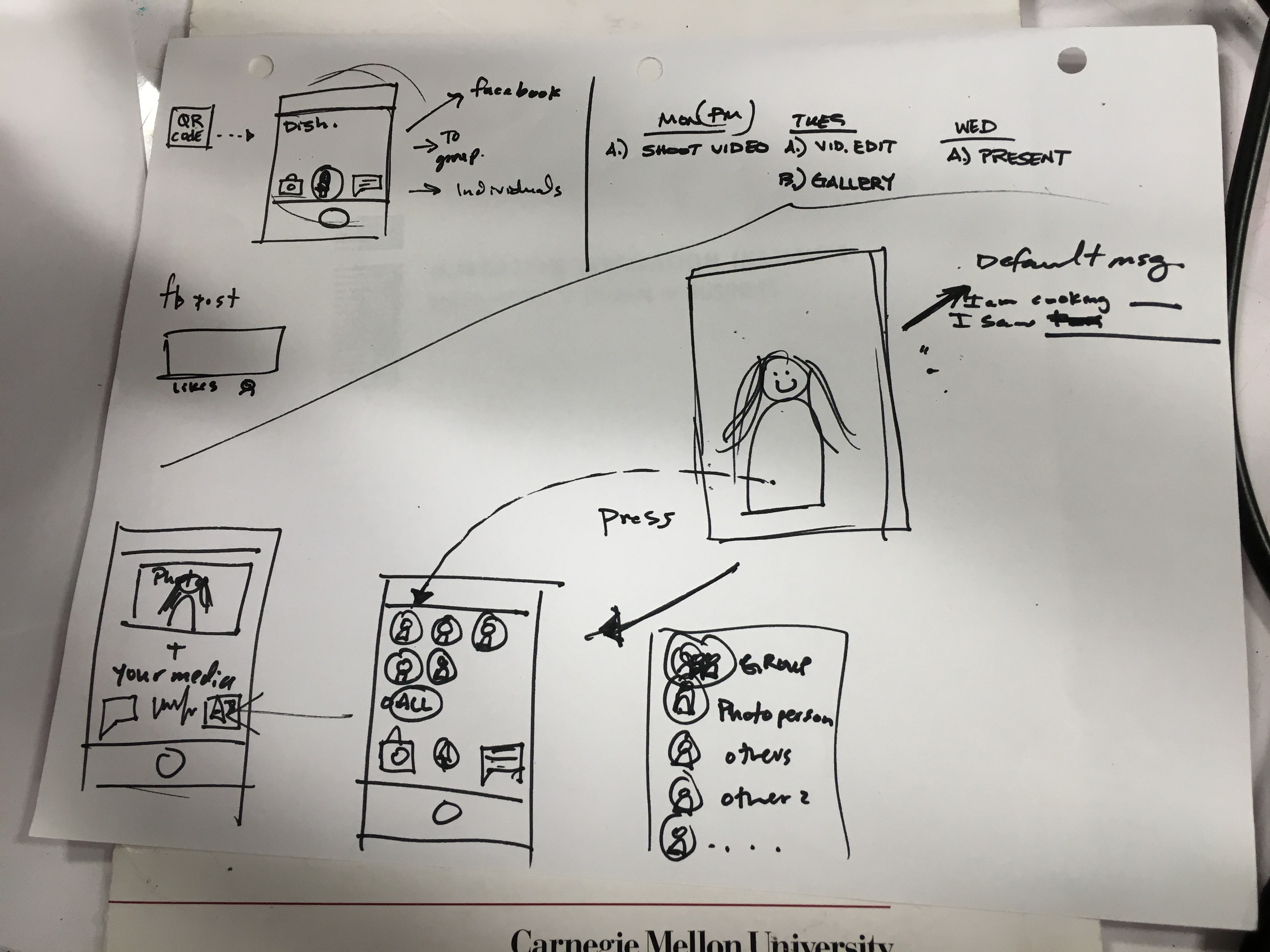
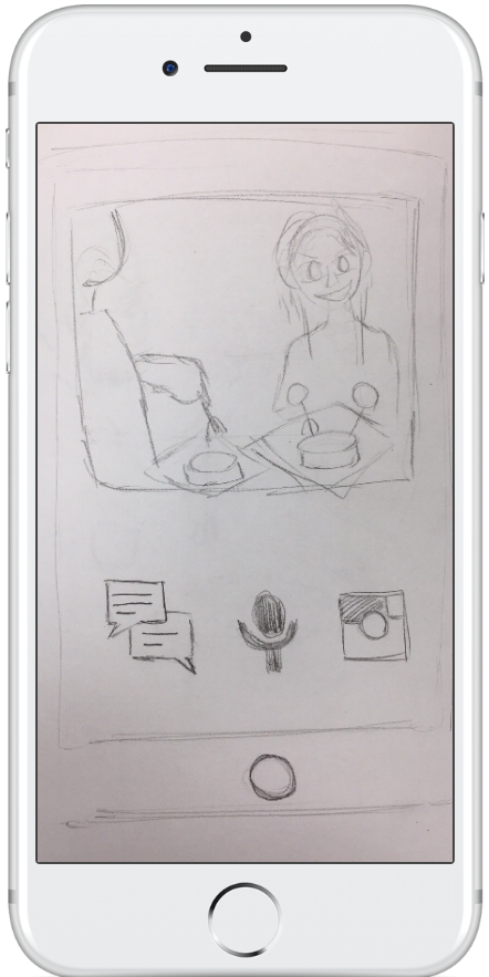
Add visual memory recall to remind users of special memories linked to each recipe. It's about more than just a recipe, it's about a bundle of memories surrounding it.
Why a Photo?
There currently is a lot of pre-existing and convenient photo sharing tech, such as smartphones, social media accounts, etc. In addition, people tend to have strong emotional reactions to photos. A picture is worth 1000 words!
Outcomes
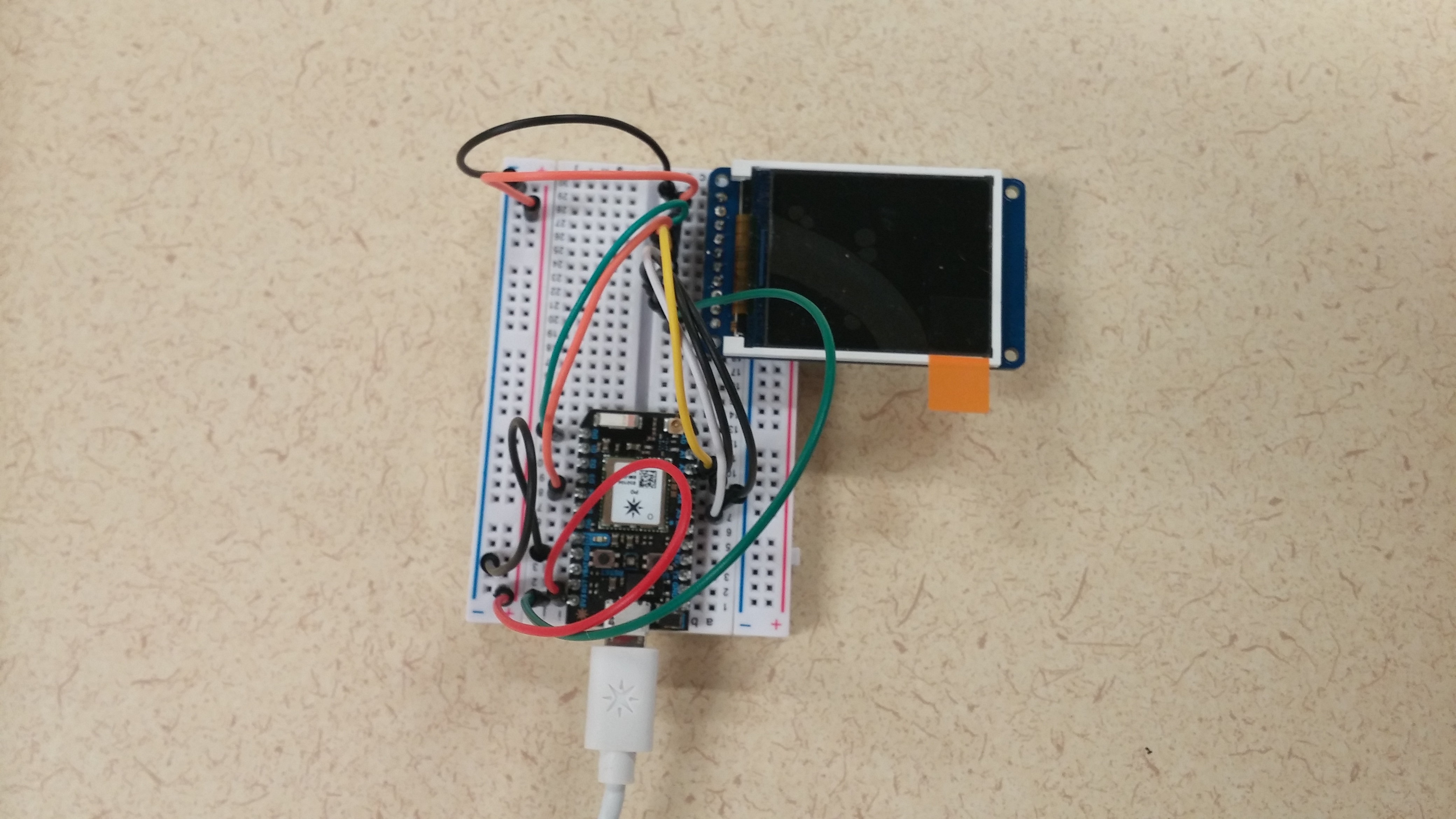
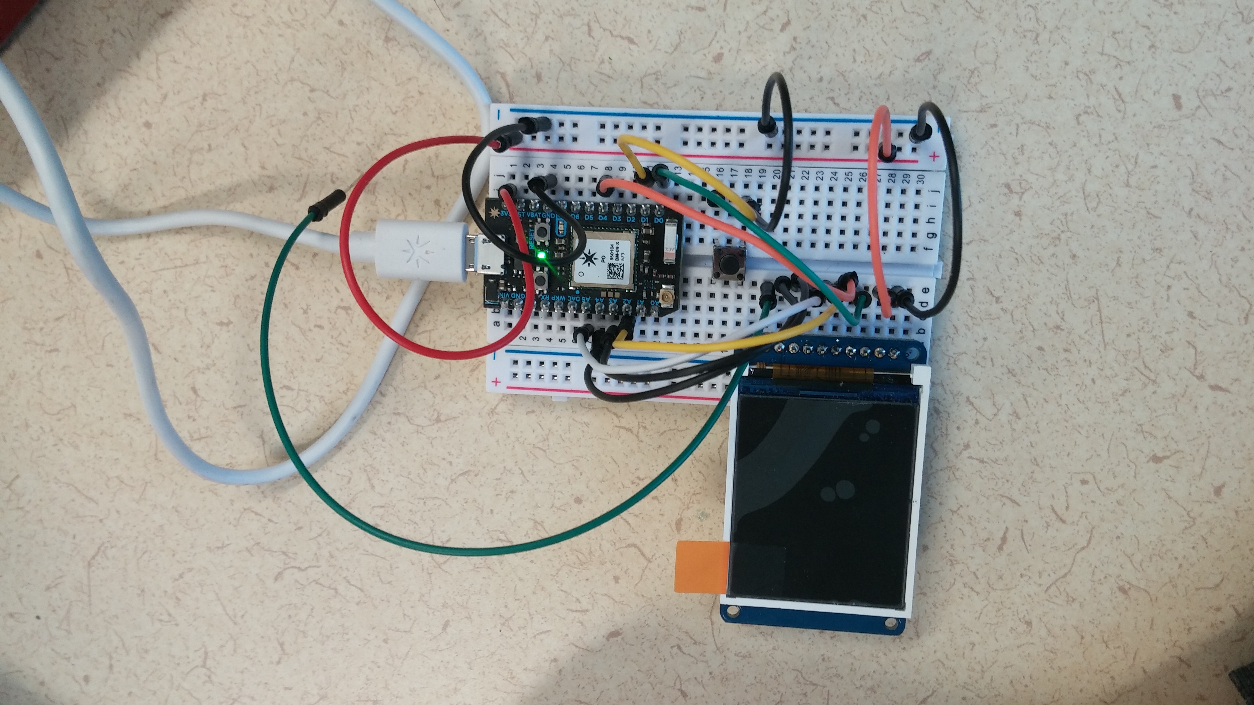
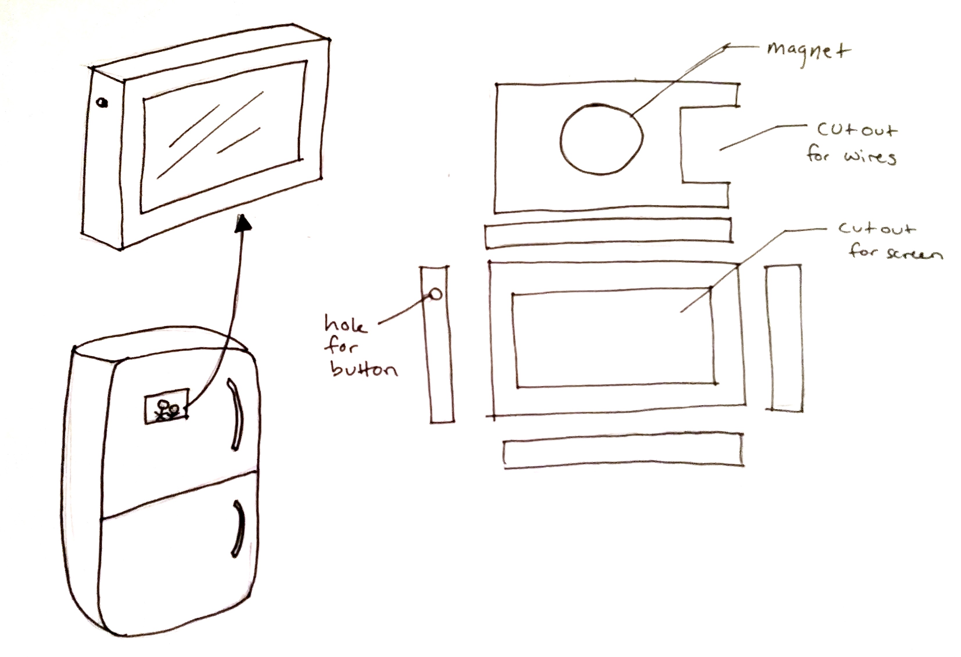
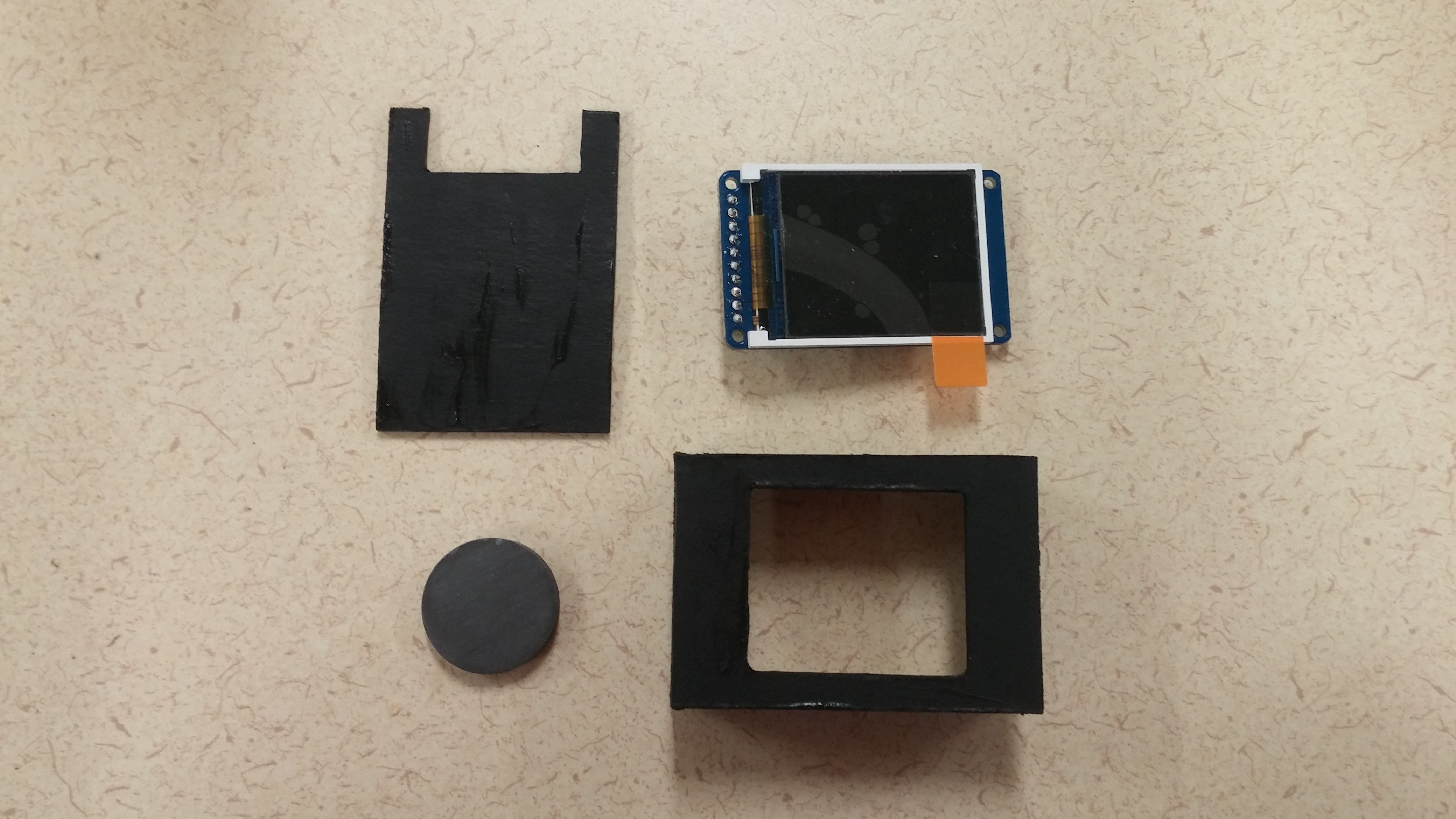
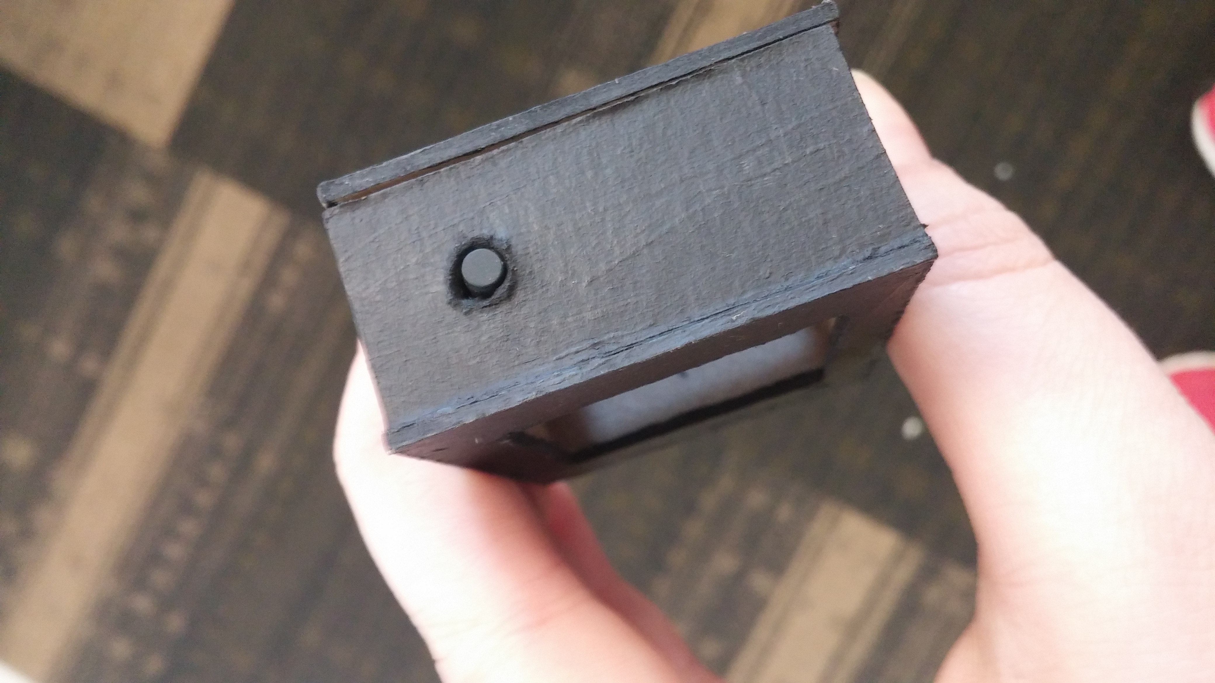
The outcome for this component was a tiny, fat, but functioning photo frame that changed photos when different recipes were chosen and sent a text when the button was pushed. In the future, we would want our frame to be much thinner, closer to the thickness of photo paper. We would also want to get a larger screen with touch screen capabilities so that the photo itself could be touched as opposed to an actual button.
Code
Note that Prototype 1.0 code reference found at this link. http://www.instructables.com/id/Your-Image-on-an-Arduino-TFT-LCD-Screen-Guide/
// The TFT driver (ST7735R)
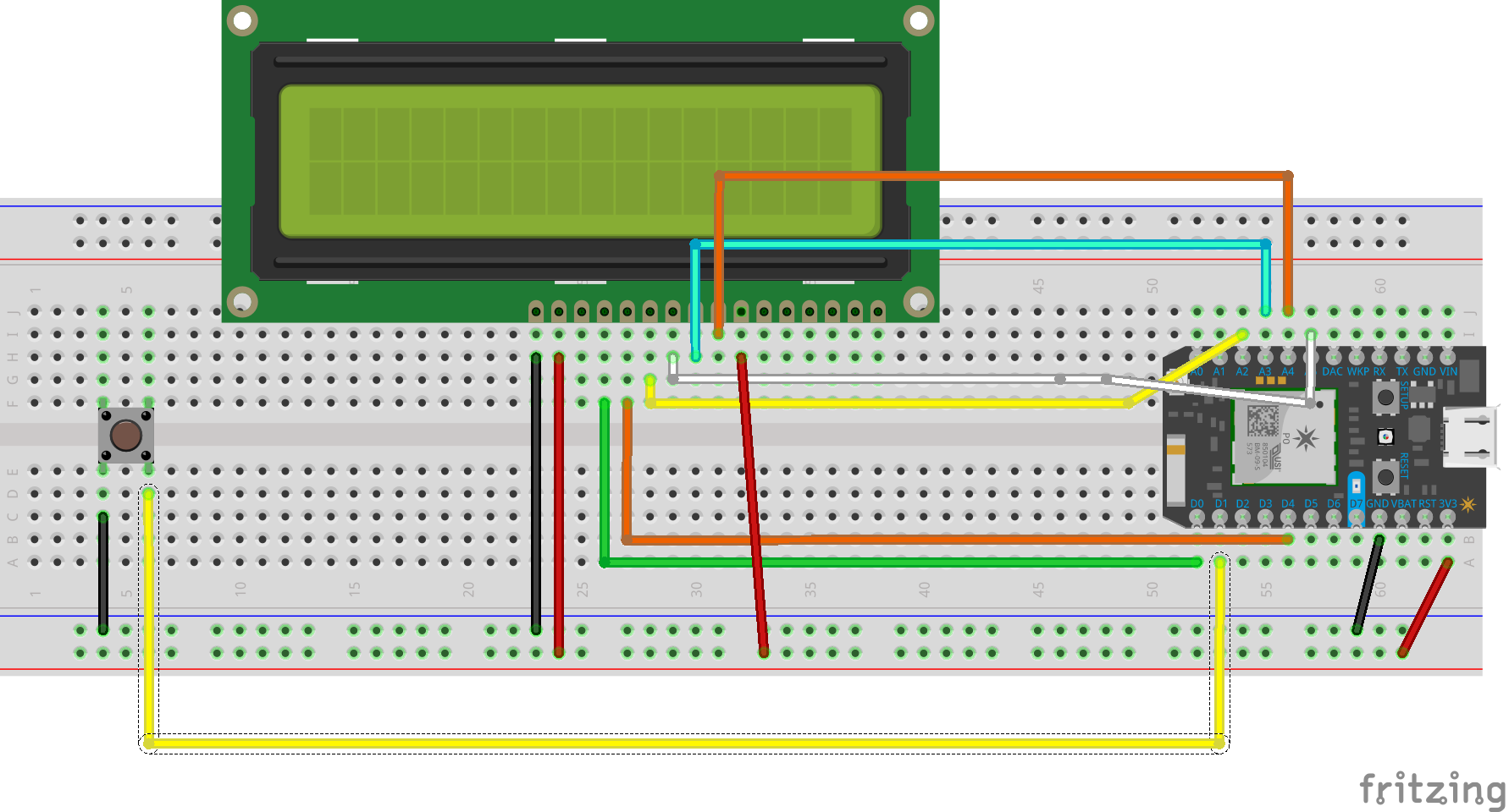
/*
Lite - this is the PWM input for the backlight control. Connect to 3-5VDC to turn on the backlight. Connect to ground to turn it off. Or, you can PWM at any frequency.
MISO - this is the SPI Master In Slave Out pin, its used for the SD card. It isn't used for the TFT display which is write-only
SCLK - this is the SPI clock input pin
MOSI - this is the SPI Master Out Slave In pin, it is used to send data from the microcontroller to the SD card and/or TFT
TFT_CS - this is the TFT SPI chip select pin
Card CS - this is the SD card chip select, used if you want to read from the SD card.
D/C - this is the TFT SPI data or command selector pin
RST - this is the TFT reset pin. Connect to ground to reset the TFT! Its best to have this pin controlled by the library so the display is reset cleanly, but you can also connect it to the Arduino Reset pin, which works for most cases.
Vcc - this is the power pin, connect to 3-5VDC - it has reverse polarity protection but try to wire it right!
GND - this is the power and signal ground pin
*/
#include "Adafruit_ST7735.h"
#include "SD.h"
// Required = Adafruit_ST7735 library
// Adafruit GFX Library
#define TFT_CS   A2 // Chip select, may use any unused A or D pin (Use A2 to start)
#define TFT_DC   D0 // May be listed as 'A0' instead of 'dc' on the display (must use this pin)
#define TFT_RST  0  // wiring to 'zero' or no pin saves you one pin.
#define SPI_SCK A3 // SCK
#define SPI_MISO  A4 // MISO
#define SPI_MOSI  A5 // MOSI
#define SD_CS    D4  // Chip select line for SD card
/**
 * 1.8 inch TFT SPI Screen ST7735 adafruit
 * Board    Photon
 * LITE     A0; alternatively if you just want it on or off wire to 3V3 and GND respectively
 * TFTCS    D5 TFT Chip/Slave Select
 * SDCS     D4 SD Chip/Slave Select
 * Vcc      5V/+3.3V
 * GND      GND
 * SCLK     A3 Clock  (must use this pin)
 * D/C      A2 command
 * MOSI     A5 Data MOSI - may be shown as SDA, connect to A5 (must use this pin)
 * MISO     A4 Data MISO - must use this pin
 * RESET    not connected
 **/
 // for read16 and read32 to work properly
 void bmpDraw(char *filename, uint8_t x, uint16_t y);
 uint16_t read16(File &f);
 uint32_t read32(File &f);
Adafruit_ST7735 tft = Adafruit_ST7735(TFT_CS, TFT_DC, TFT_RST); // hardware spi

//Button is wired to D1
int switchPin = D1;
String command = "0";

void setup(){
  Serial.begin( 9600 );
  Serial.print("Initializing SD card...");
  while (!SD.begin(SD_CS)) {
    Serial.println("failed to access SD card!");
    delay(2000);
  }
  Serial.println("OK!");
  // Test out the screen
  tft.initG();
  tft.fillScreen(ST7735_BLACK);
  tft.setCursor(0, 0);
  tft.setTextColor(ST7735_WHITE);
  tft.setTextWrap(true);
  tft.print("Lorem ipsum dolor sit amet, consectetur adipiscing elit. Curabitur adipiscing ante sed nibh tincidunt feugiat. Maecenas enim massa, fringilla");
  tft.drawLine(0, 0, tft.width()-1, tft.height()-1, ST7735_YELLOW);
  tft.drawLine(tft.width()-1, 0, 0, tft.height()-1, ST7735_YELLOW);
  tft.drawPixel(0, tft.height()/2, ST7735_GREEN);
  delay( 2000 );

  // For input, we define the
    // switch as an input-pullup
    // this uses an internal pullup resistor
    // to manage consistent reads from the device

    pinMode( switchPin , INPUT_PULLUP); // sets pin as input
    pinMode(D7, OUTPUT); //feedback

  //Subscribe to event from cook book
  Particle.subscribe("doit2017/cookbook/pagenumber/cook", getPageNum);

}


void loop() {
  // find out if the button is pushed
   // or not by reading from it.
   int buttonState = digitalRead( switchPin );

   if(buttonState == LOW){
     Particle.publish("diot2017/cooking/missyou");
     digitalWrite(D7, HIGH); //feedback
     delay(1000);
     digitalWrite(D7, LOW);
   }

   if(command == "1"){
     tft.setCursor(0, 0);
     bmpDraw( "1.bmp", 0 , 0 );
   } else if(command == "2"){
     tft.setCursor(0, 0);
     bmpDraw( "2.bmp", 0 , 0 );
   } else if(command == "3"){
     tft.setCursor(0, 0);
     bmpDraw( "3.bmp", 0 , 0 );
   } else if(command == "0"){
     tft.setCursor(0, 0);
     bmpDraw( "0.bmp", 0 , 0 );
   } else {
     tft.setCursor(0, 0);
     bmpDraw( "0.bmp", 0 , 0 );
   }
}

void getPageNum(const char *event, const char *data) { //gather event name and data from it
  command = String(data);
}

#define BUFFPIXEL 20
void bmpDraw(const char *filename, uint8_t x, uint16_t y) {
  File     bmpFile;
  int      bmpWidth, bmpHeight;   // W+H in pixels
  uint8_t  bmpDepth;              // Bit depth (currently must be 24)
  uint32_t bmpImageoffset;        // Start of image data in file
  uint32_t rowSize;               // Not always = bmpWidth; may have padding
  uint8_t  sdbuffer[3*BUFFPIXEL]; // pixel buffer (R+G+B per pixel)
  uint8_t  buffidx = sizeof(sdbuffer); // Current position in sdbuffer
  bool  goodBmp = false;       // Set to true on valid header parse
  bool  flip    = true;        // BMP is stored bottom-to-top
  int      w, h, row, col;
  uint8_t  r, g, b;
  uint32_t pos = 0, startTime = millis();
  if((x >= tft.width()) || (y >= tft.height())) return;
  Serial.println();
  Serial.print(F("Loading image '"));
  Serial.print(filename);
  Serial.println('\'');
  // Open requested file on SD card
  if (!(bmpFile = SD.open(filename))) {
    Serial.print(F("File not found"));
    return;
  }
  // Parse BMP header
  if(read16(bmpFile) == 0x4D42) { // BMP signature
    Serial.print("File size: "); Serial.println(read32(bmpFile));
    (void)read32(bmpFile); // Read & ignore creator bytes
    bmpImageoffset = read32(bmpFile); // Start of image data
    Serial.print("Image Offset: "); Serial.println(bmpImageoffset, DEC);
    // Read DIB header
    Serial.print("Header size: "); Serial.println(read32(bmpFile));
    bmpWidth  = read32(bmpFile);
    bmpHeight = read32(bmpFile);
    if(read16(bmpFile) == 1) { // # planes -- must be '1'
      bmpDepth = read16(bmpFile); // bits per pixel
      Serial.print("Bit Depth: "); Serial.println(bmpDepth);
      if((bmpDepth == 24) && (read32(bmpFile) == 0)) { // 0 = uncompressed
        goodBmp = true; // Supported BMP format -- proceed!
        Serial.print(F("Image size: "));
        Serial.print(bmpWidth);
        Serial.print('x');
        Serial.println(bmpHeight);
        // BMP rows are padded (if needed) to 4-byte boundary
        rowSize = (bmpWidth * 3 + 3) & ~3;
        // If bmpHeight is negative, image is in top-down order.
        // This is not canon but has been observed in the wild.
        if(bmpHeight < 0) {
          bmpHeight = -bmpHeight;
          flip      = false;
        }
        // Crop area to be loaded
        w = bmpWidth;
        h = bmpHeight;
        if((x+w-1) >= tft.width())  w = tft.width()  - x;
        if((y+h-1) >= tft.height()) h = tft.height() - y;
        // Set TFT address window to clipped image bounds
        tft.setAddrWindow(x, y, x+w-1, y+h-1);
        for (row=0; row<h; row++) { // For each scanline...
          // Seek to start of scan line.  It might seem labor-
          // intensive to be doing this on every line, but this
          // method covers a lot of gritty details like cropping
          // and scanline padding.  Also, the seek only takes
          // place if the file position actually needs to change
          // (avoids a lot of cluster math in SD library).
          if(flip) // Bitmap is stored bottom-to-top order (normal BMP)
            pos = bmpImageoffset + (bmpHeight - 1 - row) * rowSize;
          else     // Bitmap is stored top-to-bottom
            pos = bmpImageoffset + row * rowSize;
          if(bmpFile.position() != pos) { // Need seek?
            bmpFile.seek(pos);
            buffidx = sizeof(sdbuffer); // Force buffer reload
          }
          for (col=0; col<w; col++) { // For each pixel...
            // Time to read more pixel data?
            if (buffidx >= sizeof(sdbuffer)) { // Indeed
              bmpFile.read(sdbuffer, sizeof(sdbuffer));
              buffidx = 0; // Set index to beginning
            }
            // Convert pixel from BMP to TFT format, push to display
            b = sdbuffer[buffidx++];
            g = sdbuffer[buffidx++];
            r = sdbuffer[buffidx++];

            /*Serial.print( r );
            Serial.print( " " );
            Serial.print( g );
            Serial.print( " " );
            Serial.print( b );
            /*Serial.println( " ");*/
            //tft.drawPixel( row , col, tft.Color565(r,g,b));
            tft.pushColor(tft.Color565(r,g,b));

          } // end pixel
        } // end scanline
        Serial.print(F("Loaded in "));
        Serial.print(millis() - startTime);
        Serial.println(" ms");
      } // end goodBmp
    }
  }
  bmpFile.close();
  if(!goodBmp) Serial.println("BMP format not recognized.");
}
// These read 16- and 32-bit types from the SD card file.
// BMP data is stored little-endian, Arduino is little-endian too.
// May need to reverse subscript order if porting elsewhere.
uint16_t read16(File &f) {
  uint16_t result;
  ((uint8_t *)&result)[0] = f.read(); // LSB
  ((uint8_t *)&result)[1] = f.read(); // MSB
  return result;
}
uint32_t read32(File &f) {
  uint32_t result;
  ((uint8_t *)&result)[0] = f.read(); // LSB
  ((uint8_t *)&result)[1] = f.read();
  ((uint8_t *)&result)[2] = f.read();
  ((uint8_t *)&result)[3] = f.read(); // MSB
  return result;
}Share this Project
Found In
Courses
49-713 Designing for the Internet of Things
· 26 members
A hands-on introductory course exploring the Internet of Things and connected product experiences.
Focused on
About
The Connected Photo reminds users of fond memories related to the dish they are cooking
Created
March 4th, 2017
