


49-713 Designing for the Internet of Things
· 26 members
A hands-on introductory course exploring the Internet of Things and connected product experiences.
Alert the chef if the meat has achieved the right cooking temperature by a notification alert and visual response.
IoT Device
A Device that will send you notifications when the inside temperature of the meat has reached the predetermined level. A visual hint also would be provided.
Advantages
You don’t have to keep on checking the temperature by opening the oven door, inserting a meat thermometer, reading the temperature and repeating the process until the result is achieved.
Concern
The connection between the device and the temperature sensor inside the oven. The oven cooking temperature range between 350 t0 450 degree Fahrenheit. Our sensors are not designed for that. So I would be using the temperature sensor on a hot liquid as a prototype concept.
Working
The Device would consist of a temperature sensor as the analog input, digital output as a notification and analog output as a visual hint and a sound warning. The temperature sensor would be sensing the temperature of the inside meat and when it reaches the predetermined temperature set by the user online, the device would be enabled to sent notification via wi-fi to the user and a visual hint via an led light would be given out . The warning sound would be assisting the warning light.
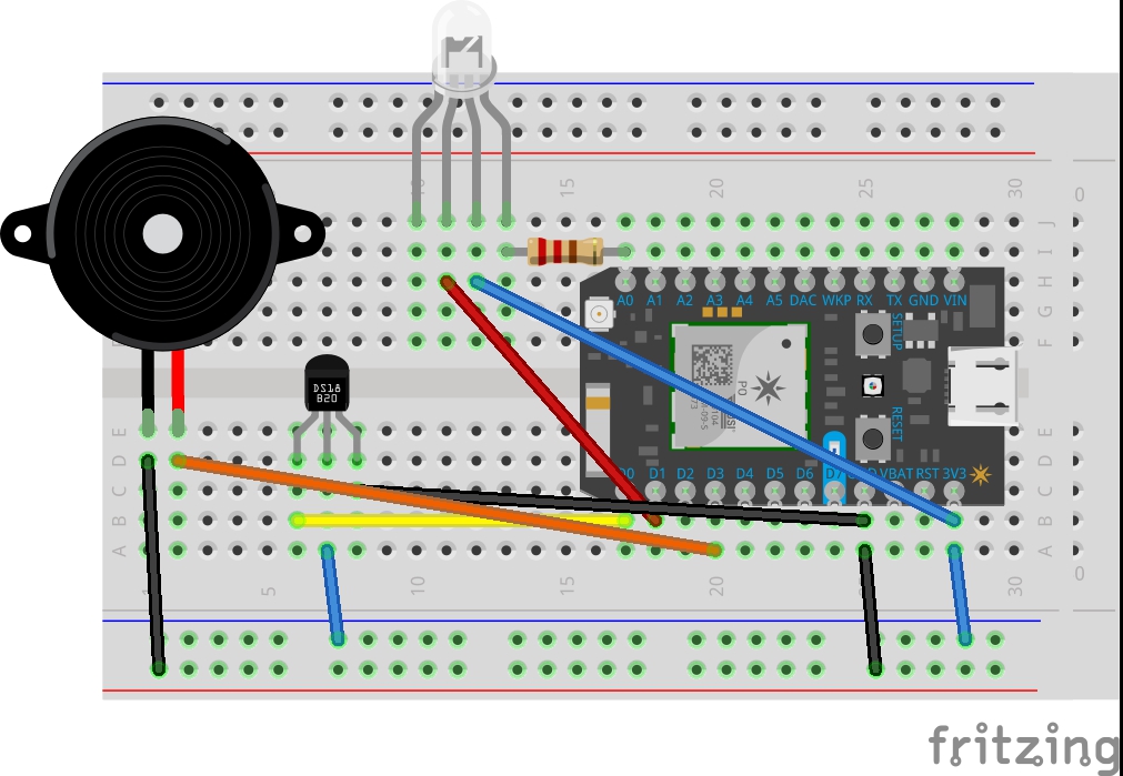
Parts
Photon, Temperature Sensor(DS18B20)-1, RGB led light bulb-1, Piezo sound, Bread board, jumper wires, resistors
“It’s another thanksgiving day. Rosie had put the turkey inside the oven and was busy preparing the other dishes for the lunch. Her Husband was busy entertaining his parents and their kids were playing around with their cousins who had come home for thanksgiving.
She kept telling herself to keep an eye on the turkey as it should be cooked to the right temperature inside. Too less and it would become undercooked and too much would make it burned. She had kept the meat thermometer ready next to the oven so that when its time she could open the oven and check the meat temperature.
Time passed by, she got the side dishes ready and was feeling content until she started to get a burnt smell.”
Brief:
I categorized the project into three targets as a thought process.
First- Make the RGB Led work with program.
Second-Make the Piezo Sound work.
Third-Make the temperature sensor work and tweak the led and piezo sound to work according to the temperature data and enable push notifications.
Inspiration Projects:
Project process
First - Making the RGB Led work.
Why RGB? The project could have been achieved with a green led and red led individually set up. But an RGB led would be cool and also help me learn to code the RGB and make it work.
Reference:
https://community.particle.io/
This blog had a program which was already tried by one of the participants and had the pictures of wiring diagram which i used to achieve the RGB output. Once i acheived the RGB output, the code was tweaked to remove the blue light and the wire was unplugged in the bread board.
int REDPin = A0; // RED pin of the LED to PWM pin **A0**
int GREENPin = D0; // GREEN pin of the LED to PWM pin **D0**
int BLUEPin = D1; // BLUE pin of the LED to PWM pin **D1**
int brightness = 255; // Full brightness for an ANODE RGB LED
void setup()
{
pinMode(REDPin, OUTPUT); // sets AO pin as output
pinMode(GREENPin, OUTPUT); // sets D0 pin as output
pinMode(BLUEPin, OUTPUT); // sets D1 pin as output
}
void loop()
{
analogWrite(REDPin, brightness);
delay(500);
analogWrite(GREENPin, brightness);
delay(500);
analogWrite(BLUEPin, brightness);
delay(500);
analogWrite(REDPin, 0);
delay(500);
analogWrite(GREENPin, 0);
delay(500);
analogWrite(BLUEPin, 0);
delay(500);
}
In this program, analogWrite was converted to digitalWrite and only Red and green pin were used.
Second - Making the Piezo work.
The Piezo wiring diagram was taken from the lab tutorials and the code executed using digitalWrite function with a simple warning tone. It produced a single long tone.
The program was tweaked to make the tone as "beep, beep beep" with delay and loop function. The tone was programmed to turn on only when the red light was on.
The RGB+Piezo program was saved as a separate file.
Third - The program set for temperature sensor was downloaded from Daragh's github account and then wiring was done according to the diagram. The temperature sensor was checked by dipping it in a cup of hot water. The cloud variables did show the change in temperature.
Fourth - The temperature sensor program was tweaked by adding the RGB+Piezo program into it. Still the temperature and RGB+Piezo were independent entities.
Final - The If else function was added to light up the RGB to red when temperature crossed 50 degree Celsius which would otherwise be green and the piezo would make the beep beep sound. The Program was linked to IFTTT to sent an SMS once the temperature was achieved. In the program, Publish function was used to send a notification to the user to alert that, " The food is cooked; Its time to eat.
Temperature readings and output recorded :
Cold- 22.25degree Celcius/72 degree Fahrenheit; Green Light On.
Warm- 25.62 degree Celcius/78 degree Fahrenheit; Green Light On.
Hot-
55.87 degree Celcius/132.57 degree Fahrenheit; Red Light On." Beep Beep" from Piezo. Notification sent through IFTTT to mobile phone.
1. If you have the idea, its just a matter of how the idea is approached with steps and necessary learning in between that makes it work overall.
2. It was quiet an experience. I was terrified in the beginning of the whole idea. But then, after reading the basics, I just started by trying the RGB Led. The program were available online and so was the board diagram. This made it easy. Then it was a matter of understanding the program and tweaking it to achieve what I wanted.
3. The Original Idea was to sense the temperature of the inside part of meat in Oven. But the available sensors and devices would not be able to handle oven temperature. Hence, the idea was downsized to measuring a hot food/liquid.
4. By doing so, I was able to learn the know hows of executing this idea and have a IOT Device which could be a real life solution with right ingredient of components.
5. The next step would be to incorporate an input medium where a temperature can be preset and then the device would start working and notify the user when its done. Or even better, maybe the IOT Device would turn off the oven after reaching the preset temperature.
6. Making music out of the piezo would be a nice experience next time.
7. Should figure out to control the notifications as once the temperature is achieved, it kept on notifying until the device was turned off or temperature came down. This could be like spamming the message box which is not desirable.
// This #include statement was automatically added by the Spark IDE.

#include "OneWire.h"

// This #include statement was automatically added by the Spark IDE.

#include "spark-dallas-temperature.h"

int REDPin = A0; // RED pin of the LED to PWM pin **A0**

int GREENPin = D1; // GREEN pin of the LED to PWM pin **D0**

//int BLUEPin = D1; // BLUE pin of the LED to PWM pin **D1**

int brightness = 255; // Full brightness for an ANODE RGB LED

int buzzPin = D3;

// -----------------

// Read temperature

// -----------------

// Data wire is plugged into port 0 on the Arduino

// Setup a oneWire instance to communicate with any OneWire devices (not just Maxim/Dallas temperature ICs)

OneWire oneWire(D0 );

// Pass our oneWire reference to Dallas Temperature.

DallasTemperature dallas(&oneWire);

// Create a variable that will store the temperature value

double temperature = 0.0;

double temperatureF = 0.0;

#include <math.h>

void setup()

{

pinMode(REDPin, OUTPUT); // sets AO pin as output

pinMode(GREENPin, OUTPUT); // sets D0 pin as output

// pinMode(BLUEPin, OUTPUT); // sets D1 pin as output

pinMode(buzzPin, OUTPUT);

// Register a Particle Core variable here

Particle.variable("temperature", &temperature, DOUBLE);

Particle.variable("temperatureF", &temperatureF, DOUBLE);

// setup the library

dallas.begin();

Serial.begin(9600);

}

void loop()

{

// Request temperature conversion (traditional)

dallas.requestTemperatures();

sin( 23423 );

// get the temperature in Celcius

float tempC = dallas.getTempCByIndex(0);

// convert to double

temperature = (double)tempC;

// convert to Fahrenheit

float tempF = DallasTemperature::toFahrenheit( tempC );

// convert to double

temperatureF = (double)tempF;

// Print out

Serial.print( "Temp in C = ");

Serial.print( tempC );

Serial.print( "\t\t F = ");

Serial.println( tempF );

if(temperature>50){

//checking if temperature is greater than 50C then,

digitalWrite(REDPin, LOW);//turn on red led

digitalWrite(GREENPin, HIGH);//turn off green led

digitalWrite(buzzPin,HIGH);//turn on sound

delay(1000);

digitalWrite(buzzPin,LOW);//turn off sound

delay(1000);

Particle.publish("Its_cooked","Its_time_to_eat");

}else{//if temperature is less than or equal to 50C then

digitalWrite(GREENPin,LOW);//turn on green led

digitalWrite(REDPin,HIGH);//turn off red led

digitalWrite(buzzPin,LOW);//turn off sound

}

delay(2000);

}A hands-on introductory course exploring the Internet of Things and connected product experiences.
Alert the chef if the meat has achieved the right cooking temperature by a notification alert and visual response.
January 26th, 2017