Pixel Away
Made by Sijia Li, Ranveer Katyal and Menghan Zhang
Found in Diot 2019: Social Objects - Part 3
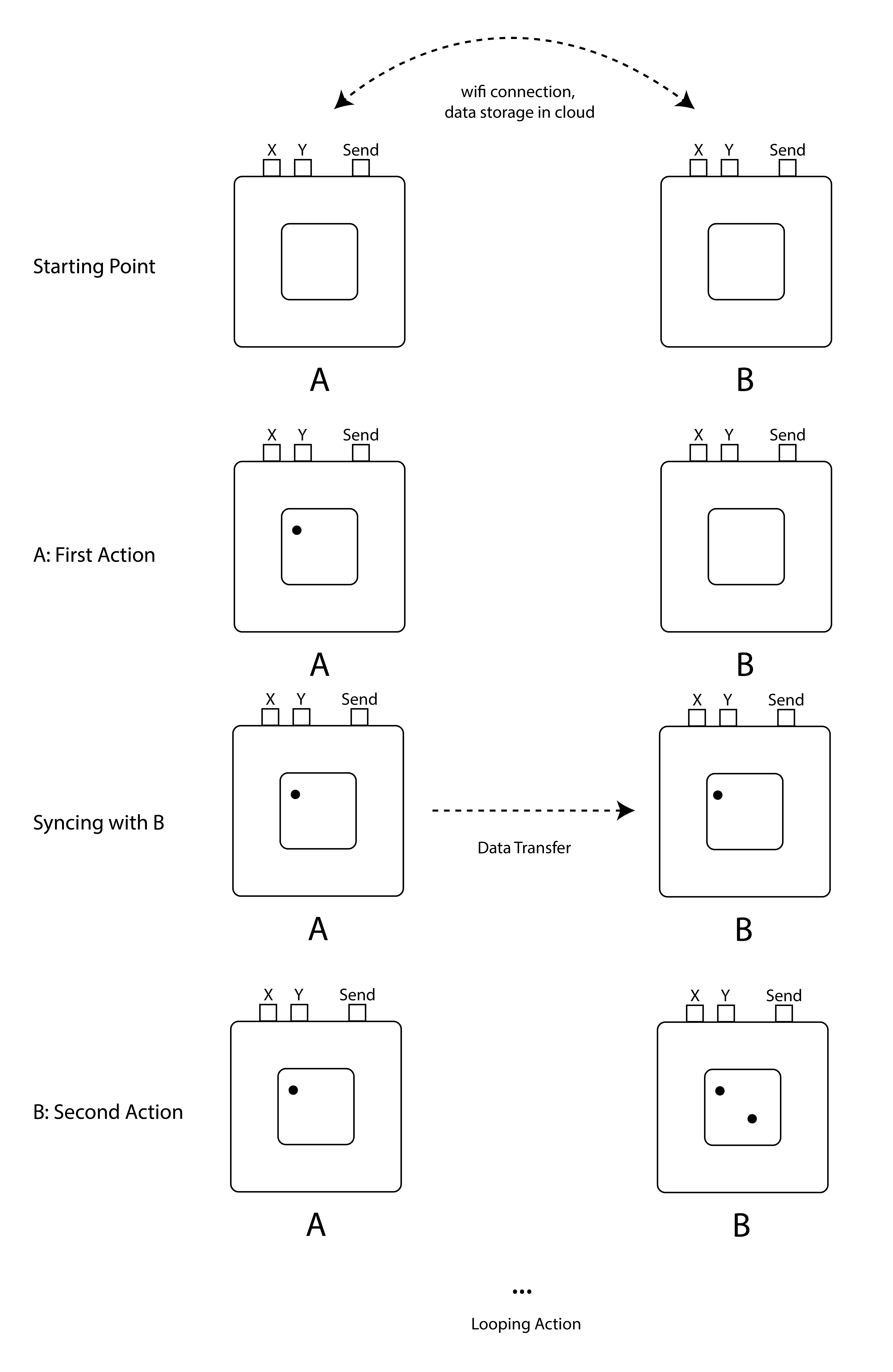
Our creative project is to help friends and couples connect with each other in a subtle and fun way. The device is a basic 8 by 8 square LED matrix and serves as a canvas for both sides to draw.
Storyboard

Process
Step 1: First Working Prototype with Neopixel
For our first working prototype, we want to create a set of two connected Neopixel devices. If one presses the button, the corresponding LED will light up on both devices.

Step 2: Get Familiar with LED Matrix
To learn how LED matrix works, we referred to the code and examples by Chrisloris ( https://github.com/chrisloris/LedControl-MAX7219-MAX7221). In this step, we successfully implemented a simple demo in which we can control the movement of LED dots on the matrix. Here is the code for this step:

Step 3: Connect Two Devices

Step 4: Design the Cubes
We made two boxes with foam board and used them as the containers of all the components. To make the product more adorable, we painted each cube with different colors.

Step 5: Assemble the Final Prototype
The biggest challenge we met here was the circuit shortcut. Since the cubes are small and the wires are easy to be pulled out from the breadboard, we used tapes to stabilize them, while resulting in wires touching each other. Finally, we solved the problem by removing the tapes.

Share this Project
Courses
49713 Designing for the Internet of Things
· 18 members
A hands-on introductory course exploring the Internet of Things and connected product experiences.
Focused on
About
Our creative project is to help friends and couples connect with each other in a subtle and fun way. The device is a basic 8 by 8 square LED matrix and serves as a canvas for both sides to draw.
Created
February 16th, 2019